Australian Geomechanics Society Sydney Chapter Symposium November 2020
Cross Passages Ground Treatment for Melbourne Metro Tunnel Project
Philippe Vincent (1), Alexandre Hubaut (1), Sin Ping Chan (2), Simon Auvergne (2)
(1)Menard, Sydney, NSW, Australia (2)Bouygues Construction Australia, Melbourne, VIC, Australia
ABSTRACT
As part of the Melbourne Metro Tunnel project, there was a requirement for ground treatment between tunnels, specifically at cross passages where the ground was identified as not being sufficiently competent to safely execute underground activities such as the safe removal of precast concrete segmental tunnel linings at cross passages and excavation of the cross passages. Cross passages CP02, CP03, CP04, CP05, and CP15 are located within soft or mixed ground conditions which required ground treatment to control groundwater ingress and/or provide suitable ground control to allow stability of mined excavation between the tunnel tubes. The proposed ground treatment principally consisted of overlapping jet-grouting columns forming a homogenous treated block installed from ground surface to depth of 30m. Further, when the cross passages treatment area intersect rock, rock grouting treatment was required to reduce the permeability of the rock mass and of the interface between jet & rock to reduce potential water inflow to the future excavation within allowable limits. The realization of those critical ground treatment required to overcome technical challenges which are detailed in the paper and include but not limited to; adapting the grouting parameters to accommodate for the high geological & geotechnical variability at each site, working near various urban assets including under and around a live rail line, maintaining alignments for both vertical and inclined columns, ensuring proper grouted diameters with sufficient overlap and remediation based on as-built 3D monitoring. To achieve this, the authors relied on a range of state-of-the-art trial at each treatment location and associated geotechnical testing, monitoring and mapping techniques some of which were used for the first time in Australia. In addition, a comprehensive regime of in-situ testing was carried out from the surface and from within the tunnel following and confirming performance of ground treatment to demonstrate that the project’s water tightness and mechanical requirements were consistently met to mitigate the risks associated with excavation of the cross passages. The performance and quality of the treatment was ultimately confirmed during the excavation of the cross passages.
1. PROJECT OVERVIEW
1.1. INTRODUCTION
The $11 billion-project of Melbourne Metro is the greatest ever transport infrastructure project in Melbourne. Scheduled to open in 2025, the purpose of the metro tunnel is to free up space in the city loop to run more trains to and from the suburbs by taking the busiest train lines through a new tunnel under the city. The Project comprise twin 9-kilometre-long by 6.9m internal diameter tunnels providing North-South underground rail connection across Melbourne Central Business District from Western Portal near Kensington Road to Eastern Portal near Chapel Street, South Yarra. New underground railway station will be constructed at Arden, Parkville, CBD North, CBD South, and Domain. As part of the works, 26 cross passages are to be constructed at approximately 230 metres apart along the tunnel alignment. Cross Passages are constructed from below ground within the tunnels after the tunnel boring machines (TBMs) have passed through. These passages are an important safety feature that allow people (including emergency services) to move from one tunnel to the other in the event of an emergency as well as hosting maintenance facility for drainage.
1.2. TECHNICAL CHALLENGES
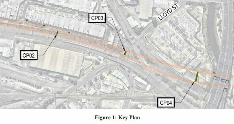
As part of the works, there was a requirement for ground treatment between tunnels, specifically at cross passages where the ground has been identified by the Designer, as not having the required parameters to safely execute underground activities such as the safe removal of precast concrete segmental tunnel linings and mined excavation of the cross passages under the threat of high water and earth pressure. Cross passages CP01, CP02, CP03, CP04, CP05 and CP15 are located within soft or mixed ground conditions which require ground treatment to control groundwater ingress and provide suitable ground control to safely execute the underground works. This paper specifically presents the ground treatment design & construction at CP02, CP03 and CP04 (Figure 1).
Excavation of an underground cross passage is a high-risk activity and numerous associated accidents were reported in the literature. In case of an accident during the opening of a tunnel segment and the mined excavation between the tunnel tubes, the groundwater and soils might flow into the tunnel, causing large amounts of ground loss, and induce excessive ground movements which might cause permanent distortion to the tunnel shape and movement of the segments which make up the tunnel lining, ultimately damaging the completed tunnels. The influx of water/soil might also provoke piping and subsequent ground subsidence and formation of sink hole above the tunnels propagating to the surface. Such event causes delay & increase of cost for the project and may have significant impact on surrounding infrastructures. In light of the above consideration, the designer had considered several complementary risk mitigation strategies for the safe excavation of the cross passages with due consideration that resulting discontinuity of the improved ground could create a path for the invading water. Additional measures include water leak test and probe grouting from the tunnel.
1.3. CONTRACT APPROACH
The Cross Yarra Partnership Consortium (CYP) consisting of John Holland, Lendlease and Bouygues Construction Australia have been selected to design and construct the Metro Tunnel (Tunnels and Stations PPP Project) for the State of Victoria (RPV).
In turn, and in order to perform the highly technical ground stabilisation works, the CYP consortium awarded Menard Oceania (MO) as specialist geotechnical sub-contractor for all the ground treatment works. The award process involved numerous consultations during which the scope of MO was adjusted several times in order to allow for appropriate risk sharing and mitigation measures to be included in the contract. Both CYP and MO worked in close collaboration to identify potential risks and effective measures and scenarios to deal with them. The award was based on the understanding that the limited amount of geotechnical information available would require detailed trialling at each CP.
2. CROSS PASSAGE GROUND TREATMENT DESIGN
2.1. GEOTECHNICAL CONDITIONS OF THE CROSS PASSAGES
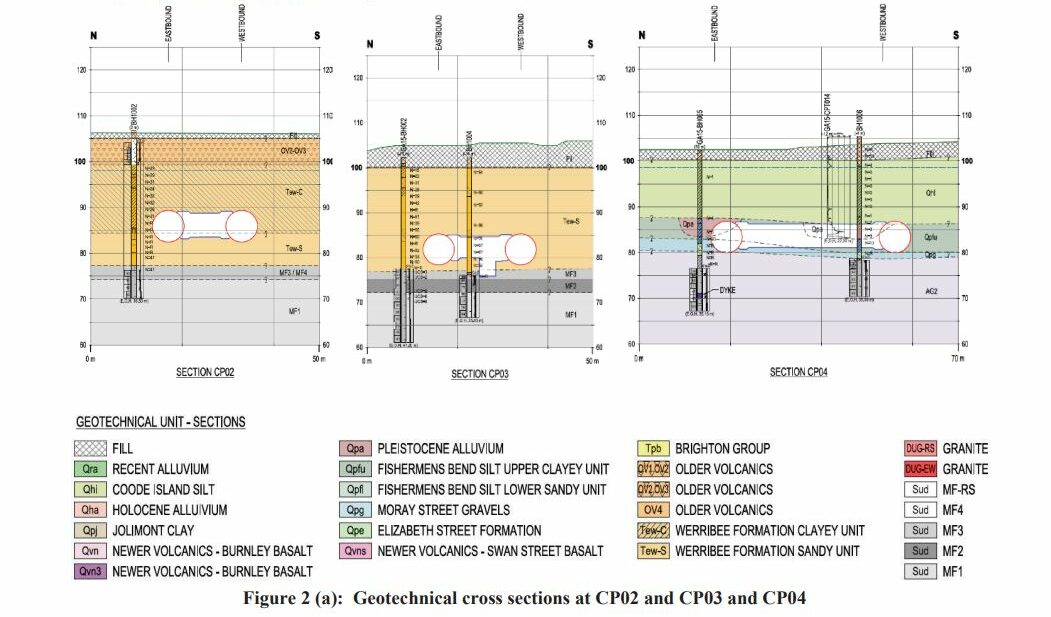
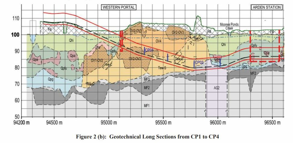
The Silurian age Melbourne formation (also known as the Melbourne mudstone) forms the bedrock in the Melbourne area, it is comprised mainly of siltstone interbedded with sandstone and characterized by persistent bedding varying typically between 10 to 300mm thick. Above the bedrock tertiary deposits are observed on the western side of the project locally such as the Werribee formation (hard clay & dense sand/gravel mainly) and older volcanic (fractured basalt mainly). Then quaternary Pleistocene deposits such as Fishermens bend silty and Moray street gravel and Quaternary Holocene deposits such as the Coode island silt are the main geological formation impacting the ground treatment works.
Due to this complex geological context, each cross-passage location presents specifics and challenging ground conditions such as for example hard clay in CP2 underlying Older Volcanic, highly variable Melbourne formation rockhead in CP3 and soft clay in CP4 (Coode Island Silt).
2.2. GROUND TREATMENT DESIGN
2.2.1 Design philosophy
The proposed ground treatment principally consisted of overlapping jet grouting columns forming a homogenous treated block installed from ground surface prior to TBM tunnelling with the intent to:
- provide sufficient strength and treated volume around the mined excavation between the tunnels tubes to allow safe execution of cross passages excavation works
- minimise the seepage of groundwater into the mined excavation between the tunnel tubes during execution of cross passages excavation works. The overall permeability of mass Jet grouting treatment is governed by defects. Such defects may play a minor role on the overall seepage processes if jet grouting is carried out in fine grained soils, whereas they may become relevant in granular soils because of the localised flows through the untreated soil portions.
- provide suitable durability for the intended life of the proposed improvement and until construction of the permanent lining (about 2 years after treatment block construction).
Further, when the cross passages treatment area intersect rock, rock grouting and interface between jet & rock treatment was required to reduce the permeability of the rock mass and interface to reduce potential inflow to the future cross passage excavation. The rock grouting was intended to target all joints, faults, bedding planes in order to create an acceptable seal to achieve the performance requirements
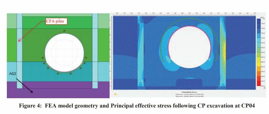
2.2.2. Numerical Modelling
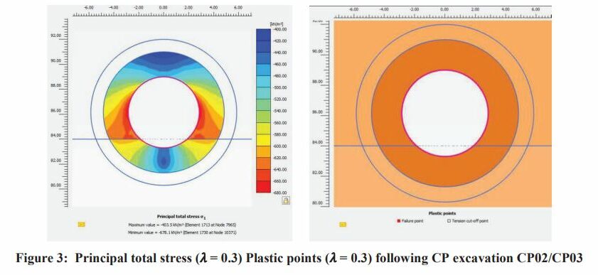
The stress and plastic yielding in the jet grouting block was assessed using Plaxis 2D FEM model. Stresses developed within the jet grouting block were assessed in 2D plane strain models for each CP. Two different load deconfinement ratios ߣ) 0.3 ܽ݊݀ 0.7) have been considered in order to evaluate the interaction between the soil and the structure. Different values of the thickness of the ground treatment around the opening were investigated and the improvement of ground
strength ܴc to identify the values at which the plastification of the soil is sufficiently reduced. The front stability for those CP was studied according to the methodology developed by Cornejo & al. During the design stage of the temporary support of the cross passages, the jet grouting block has been modelled with an increased cohesion and Young modulus to define the temporary support.
At CP04, considering the length of the CP and the presence high hydraulic conductivity gravel layer above rock, the ground treatment consisted of unreinforced Continuous Flight Auger (CFA) secant pile walls made of weak concrete forming a 30.4m x 10.01m rectangular box and four cross walls installed to rock. In addition, jet grout blocks made of overlapping jet grouting columns were required to form plugs between the CFA cells and at the collar location between the tunnel and cross passages. Stresses developed within the jet grouted blocks were assessed in Plaxis 2D plane strain models.
2.3. GROUND TREATMENT DESIGN CRITERIA
Following detailed Finite Element Modelling, seepage and drawdown assessment, it has been found that the required thickness of the extent of the jet grouting treatment zone around the CP and TBM excavation vary between 2 and 3m depending on the cross passage with the requirement to achieve a permeability of 1.10-7m/s to 5.10-7m/s . The minimum required unconfined compressive strength at 28 days was set at 1.5MPa for CP02, CP03 and CP04. The minimum required Young Modulus of 225MPa was specified at CP04.
3. JET GROUTING GROUND TREATMENT
3.1. SITE LAYOUT CONSTRAINTS
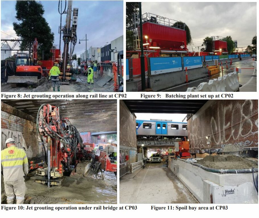
The ground treatment was installed in a challenging urban environment. This requires handling of complex challenges for safe construction and to minimise impacts on existing buildings, structures, utilities and the public. The cross passage CP02 is located directly beneath operating rail lines requiring the ground treatment to be carried out from the surface with a drilling inclination angle up to 32 degrees. The jet grouting ground treatment block was constructed at the depth of 18m to 27m. Live utilities including a major gas main was running through the working area requiring adjusting the location of the drilling entry points around an exclusion zone.
The ground treatment at cross passage CP03 was constructed at the depth of 18 to 26 m under a MTM rail bridge adjacent to a live road. A majority of the works were carried out under a 3.1m low headroom restriction in close proximity to electricity and water utilities. Inclined drilling for grouting works were required to avoid existing service utilities and the MTM rail bridge. The ground treatment at cross passage CP04 was as challenging requiring the installation of inclined jet grouted columns at the westbound plug due to overhead high voltage power lines and the operating rail lines.

The jet grouting batch plants, cement silos and high pressure grout pumps were containerised and established along the operating rail lines at the location of CP02 compound. Grout lines was run from CP02 site compound to CP03 work front.
The jet grouting operation was carefully monitored during all phase of the execution to prevent collapse of borehole and subsequent blockage which might lead to heaving and lateral ground deformation causing distress on the adjacent structures and buried utilities. A direct circulation of polymeric slurry was used in the drilling phase to sustain the borehole walls. During jet grouting, a visual observation of the flow and features of the spoil return at the collar was maintained at all times. The management of the spoil collection, storage and subsequent evacuation was particularly challenging considering the dense urban condition and tight working area. Following pumpability test of the generated spoil during field trial, Menard adopted a high suction capacity impeller pump to evacuate the jet grouting spoil from the rig to above ground spoil bays established by CYP. The wet spoil was left to set over night and separate from excess water and later dispose of at a rate that maintains sufficient storage area to accommodate spoil delivery from the jet grouting activity.

3.2. CONSTRUCTION FIELD TRIAL
3.2.1 Overview
Considering the highly variable nature of the geotechnical conditions encountered, extensive field trials was performed at each cross-passage location to verify the relationship between jetting energy and associated jet grout column diameter. Pre-production test columns are generally jetted near the ground surface and exposed by excavation to allow for visual measurement and inspection of the columns in order to establish the jetting energy versus column diameter relationship. Due to the jetting depths involved on this project, the use of shallow columns was not practical because the near-surface soils in the available test area are made of fill material that is not representative of the deep Werribee Formation that is present on CP02 and CP03 and other geotechnical units encountered on CP04 and to be treated at the CP elevations. Also, the ground water pressure and the overburden stresses at depth differ substantially from the near-surface conditions and an effective correlation cannot be made between shallow test columns and the deeper production columns.
Considering near surface ground conditions are not representative of the production works and excavation and visual inspection of columns at the required depths is not practical, Menard proposed to use a combination of CYLJET electric cylinder method® (downhole geophysics) and cored borehole inspection. CYLJET® provided an overall understanding of the column continuity, and cored boreholes allowed to punctually confirm the CYLJET® result and provide visual information on the treated material as well as recovering samples for strength and permeability testing.
An additional method which allowed information to be obtained on the achieved diameter based on the observation of the effect of jet grouting within inspection holes placed at different distance parallel to the centreline of columns was trialled. The monitoring holes were positioned at variables distances around the injection holes to check if the jet is able to cover the respective distances at variable depths. It was proposed to insert painted small diameter pipes along the
measuring verticals, which were then retrieved after treatment to observe if the jet action eroded the paint on the different pipes.
Finally, another control introduced relied on the analysis of the variability in density of the spoil return during the Jet grout columns sequenced installation. Following completion of the primary columns, density of spoil recovered during jetting of secondary columns is lower than that of the primary columns. This is because during the installation of the secondary columns, the volume of untreated ground is reduced by the area contained within the primary-secondary overlap. As a result, spoil density of secondary columns is closer to that of the grout density. A further decrease in density during installation of tertiary columns is also expected. A close monitoring of the evolution of the spoil permitted to assess the anticipated variations in column diameter and validate the consistency in overlap ratio throughout the extent of the treated block.
3.2.2 Construction Field Trial construction sequence
Construction field trials generally consisted of a minimum of three trial panels made of three overlapping jet grouted columns using different sets of injection parameters to adjust and select the most efficient jetting parameters which best suit the encountered ground conditions for production.
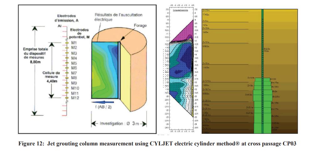
An initial CYLJET calibration hole was drilled and equipped with a PVC slot pipe in the untreated ground to measure its natural resistivity. Following the installation of primary column in each field trial panel, CYLJET readings were taken at the centre of the columns to measure the treated ground resistivity and assess the achieved column diameter through inversed contrast. Following installation and interpretation of achieved diameter on the primary columns, secondary and tertiary columns was installed at the condition that measured diameter of the primary columns were found satisfactory. Following a minimum waiting period of 7 calendar days after the installation of the overlapping jet grouting columns, vertical fully cored boreholes was carried out in the overlap zones and triple point to verify the column diameter and demonstrate the quality and continuity of the grout material in the installed columns.
3.2.3 CYLJET Electric Cylinder® Method
The Electric Cylinder® method developed and patented by SIXENSE consists of recording and analysing the potential differences generated by an induced electric current around a borehole. The electric monitoring field around the hole takes the form of a cylinder up to about 5 to 10m in diameter, depending on the electrical resistivity of the ground and instrumentation system employed. Deflections in the resistivity equipotential lines identify features such as voids, loose
zones, clay beds, etc. The method was originally used to detect anomalies such as karsts, shear faults, groundwater leaks, etc., for example when probing ahead of a tunnel boring machine.
When applied through a jet grouted column, the CYLJET® method makes use of the strong contrast in resistivity between the ground and the column material containing cement. The influence of this jet grouted material mass distorts the equal resistivity contour lines. The electrical resistivities of the ground and of the soil cement forming the column being known, a computer can simulate the shape of the resistivity contour lines under the influence of columns of various diameters. It is then simply a matter of comparing various simulations with the actual instrumental field readings to find the diameter of the column.
In most cases, the resistivity of the ground in place is several tens of ohm-m, while the jet grouted column material registers only a few ohm-m. However, column resistivity increases sharply over time, as the material hardens. After a few days, the ground/column resistivity contrast diminishes, and eventually reverses when the column has fully hardened.
Due to the presence of saline groundwater at CP02 and CP03, measured ground resistivity was very low and comparable to that of the fresh jet grouted column material. Unlike the usual situation with fresh groundwater, it was necessary to wait several days or weeks for the grout to set and resistivity of the jet grouted material to rise well above that the ambient environment before measurements are made. At CP02, a 16 days setting period was required to allow the grout to reduce conductivity enough to differentiate from the charged ions in saltwater.
Thanks to use of this patented technology, the project team was able to refine the accuracy of the estimated column diameter to within +/-150mm but also and importantly to track down the evolution of JG column diameters with depth enabling to adjust the JG parameters based on the varying geotechnical profiles encountered.
3.3.4 Full depth Cored Borehole and associated testing
The trialled overlapping jet grouted columns was fully cored at their intersections to verify closure of the columns and to confirm the achievement of a high homogeneity of treatment. Additionally, by drilling boreholes at different distance from the column axis, information on the average diameter and on possible defects of treatment was observed. UCS testing on retrieved core samples and laboratory permeability testing was carried out on retrieved core samples. In situ
permeability testing on cored boreholes such as falling head tests and lugeon test (ie packet test) was carried out to assess the permeability of the ground treatment and validate the jet grouting parameters prior to production. Drilling deviation of installed jet grouted columns and cored boreholes was measured.

3.4. PRODUCTION PERFORMANCE TESTING
3.4.1 Jet grouting layout & design philosophy
In the case of the depths involved for the ground treatment of the cross passages, the potential drilling deviation associated with depths of 19-30m would result in an excessively tight column layout with high risk of shadowing effect. Given the complexity of the project, Menard measured drilling deviation at depth using the TIGOR system developed by Jean Lutz to control alignment and deviation of jet grouting columns. We note that this system allows to calculate the deviation of
the drilling only when the drill bit returns to the surface at the completion of the JG column installation.
In order to control the ground treatment continuity and homogeneity, the following approach was adopted:
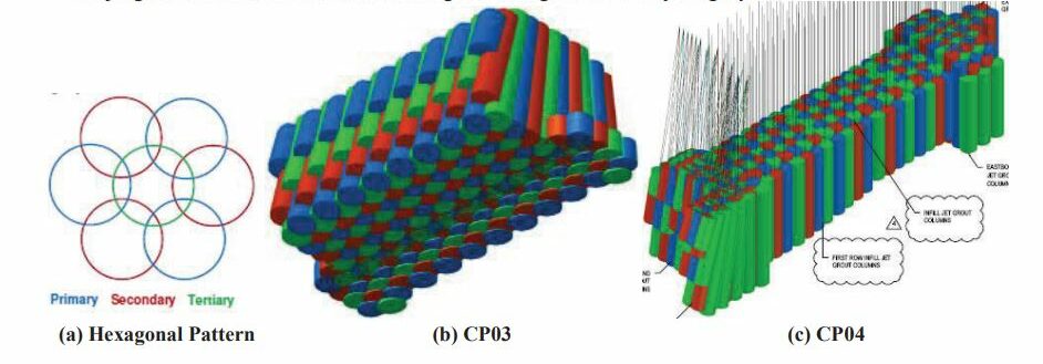
1) Prepare triangular pattern layout based on expected maximum deviation (ie. 0.5%) JG columns was installed using the primary/secondary/tertiary sequence with tertiary columns filling the remaining intersection between already jetted primary and secondary columns. The working pattern within the global layout
consist of a hexagonal pattern of three primary columns and three secondary columns at the nodes of the hexagon and one tertiary column inside the six perimeter columns. Figure 14 (a) below shows a typical hexagonal pattern for the jet grout columns taken from within the global triangular column spacing layout.
2) Drill and install primary columns
3) Measure and record drilling deviation of the primary columns and then produce a 3D plan view of the as-drilled primary hole locations and primary JG columns.
4) Once this plan view was prepared and reviewed, the secondary column layout and work sequence was re-assessed. Where the drill-hole deviation precluded the use of the original design pattern, the column diameter and sequence was adjusted based on the as-built JG pattern.
- a. When the drill-hole deviations are below 0.5%, no adjustment is necessary.
- b. When the drill-hole deviations are above 0.5% in the order of 1%, the approach is to adjust the diameter of the secondary column and adjust drilling position.
- c. Larger drill deviations can result in changing the jetting sequence, jetting adjacent columns fresh-and-fresh,
and possibly installation of additional columns.
5) Drill and install secondary columns
6) Repeat steps (2) to (4) for tertiary columns.
A total number of 164, 199 and 290 jet grouted columns were installed at CP02, CP03 and CP04, respectively for a total of 15,752m3 of treated material. A total of 15,993 lm of drilling were carried out with a variable depth of 19 to 30 meters. The jet grout column diameters typically ranged from 1.8 m to a maximum of 2.0 m. The jet grouting works at CP02 and CP03 was carried out concurrently between March and September 2019. The jet grouting operation at CP04 was carried out between May 2019 and July 2020. Jet grouting works was carried out on double shifts to meet the stringent program requirement.
3.4.2 Selection and Monitoring of jet grouting parameters
Based on observation derived from JG field trials, the jet-grouting parameters were chosen to have a jet-grouting specific energy varying between 80 to 130 MJ/m depending on the ground condition and target diameter. Additional CPTs were carried out at CP04 to verify the strength of Coode Island Silt which SPT-N values were zero and subsequently assisted at defining the JG parameters. Triaxial test were also carried out on CP02 to confirm the strength of the hard clay Tew-C unit.
JG drilling and injection parameters were continuously monitored throughout execution by Jean Lutz automatic acquisition system, data logger and software to process data and to plot them on a computer screen. JG parameters were predetermined following validation of the construction field trial. Therefore, the aim of routine monitoring of jetting parameters was to verify the conformity of the injection parameters (Fluid flow rate and pressure, rotary speed, withdrawal speed, etc). Grout specific gravity and March cone viscosity was measured and recorded from grout samples taken directly from the batch plant agitators on a regular basis.
3.4.3 Continuity and Homogeneity of jet grout structure
Inclined cored boreholes were carried out in the jet grout mass treatment to demonstrate quality of the grout material in the installed columns. Core samples was examined for continuity and homogeneity of grouted material. Verification coring locations were selected by CYP Geotechnical and Design team and were selected in a potential gap in the treatment block at the intersection between columns, identified in the Menard as-built 3-D model.
3.4.4 Physical and mechanical properties 7of the jet grout material
The conformity of the ground treatment was verified by means of UCS testing on wet grab samples, UCS testing on retrieved core samples, laboratory permeability testing on retrieved core samples and in situ permeability testing on cored boreholes such as falling head tests and lugeon tests.

4. CROSS PASSAGE ESXCAVATION
4.1. PROBE HOLDE DRILLING & GROUTING PROGRAM
Use of probe hole testing prior to breakout of tunnels for construction of cross passages was adopted to avoid the consequences of unexpected encounter with high permeability zones or zones where pre-treatment has not been fully effective. A probe hole drilling & grouting program was established for each cross passage to avoid unexpected exposure to conditions which could be hazardous to the construction workforce or could give rise to water inflows that could induce
progressive material washing leading to adverse environmental impacts or surface settlements.
Anticipated flow rates and associated trigger levels were nominated to indicate the potential for seepage to the completed cross passage in excess of rates which could give rise to adverse impacts. For cross passages in treated ground, probe holes which are at least 50% of the length of the cross passage yielding sustained flow from a single probe hole of less than 30% of the predicted/target total flow to the completed cross passage was considered satisfactory for opening of the
excavation. Aggregate sustained flow to multiple probe holes of less than 50% of the predicted/target flow to the completed cross passage was considered satisfactory for opening of the excavation. Recommended trigger flow for single and multiple probe hole varied between 0.07-0.15L/s and between 0.1-0.2L/s respectively. Equivalent maximum permeability varied between 1.10-7 to 5.10-7m/s.
Probe holes was drilled at angle varying between 2 to 16 degrees and depths ranged between 8 to 26 meters from inside the main tunnel. The probe hole testing campaign met the acceptance criteria set out by the CYP design team. The level of water inflow and permeability requirement of 2, 1 and 1 lugeon for cross passages CP02, CP03 and CP04 respectively was successfully met. No additional probing holes and pressure grout injections were required to meet the performance criteria.

4.2. REMOVAL OF PANELS AND EXCAVATION OF TREATED SOILS
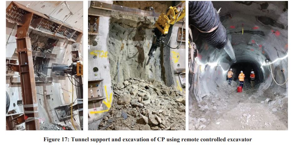
Following installation of tunnel support to prevent distortion of the main tunnel, probe drilling and subsequent removal of precast concrete segmental tunnel linings at cross passages, mined excavation was carried out in section limited to 1500 mm using remote control demolition robots. The temporary support consisted of shotcrete of 200 to 250mm thickness and two layer of wire mesh.
4.3. MEASUREMENT OF AS-BUILT COLUMNS
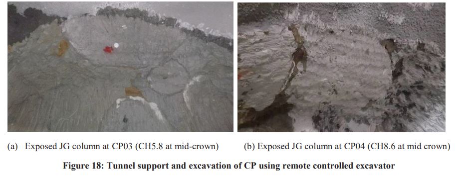
Following opening of the cross passages, primary jet grouted columns at the crown was exposed by mined excavation and allowed for visual measurement and inspection of the achieved column diameter. The measured diameters were in line with the design. Exposed as- built columns were mapped and checked against the 3D as built models which confirmed the accuracy of the drilling deviation measurement.
5. INSTRUMENTATION & MONITORING
As in the case of any large tunnelling project, the potential for ground movement exists where excavations would be undertaken as part of Melbourne Metro works. Ground movements may occur above and adjacent to Melbourne Metro works due to underground excavations and consolidation settlement of compressible soils due to groundwater drawdown. Buildings, utilities and civil infrastructure such as roads, rail lines and bridges may be subjected to the effects of ground movements (settlement) caused by the mined excavation of the cross passage portals and/or associated drawdown effects
5.1. EXTERNAL TUNNEL MONITORING: SURFACE MOVEMENT
Considering the critical structures and utilities in vicinity of the ground treatment areas (Active railway, >100yr brick wall with shallow brick-foundation, >100yr large dia. Brick barrel sewer, gas mains and HV cable etc), intensive monitoring with close follow up against the highly restricted allowable displacement had been carried out covering the ground and structural displacement and change in groundwater level/pressure. Fluctuated background displacement with a range was identified, increasing the challenges on identifying the early warning of the displacement related to the ground treatment works. State of the art real time monitoring system including total stations network, automatic tiltmeter and pressure sensor piezometer, was adopted by CYP.
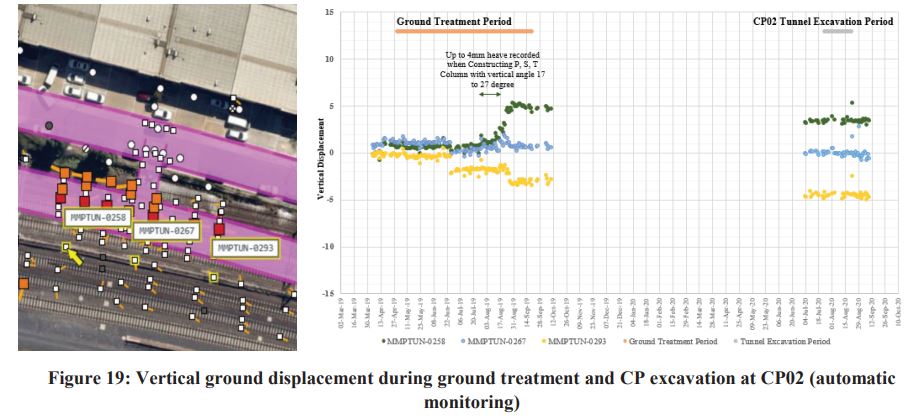
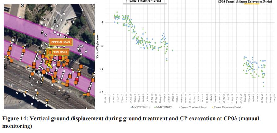
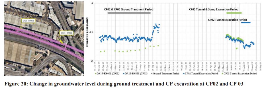
With the detailed design on the treatment parameters and sequence with review in according to the ongoing monitoring analysis and interpretation, the vertical displacement associated with the ground treatment works was strictly controlled to within +/-5mm (the min. design Amber Trigger) even at the time constructing the largely inclined column (columns with max. 32 degrees inclination) at cross passage CP02. Generally stable groundwater level recorded during the ground
treatment period. Negligible ground displacement was recorded during the cross passages tunneling excavation with no unexpected change in groundwater level recorded. This indicate the treatment block has achieved the design required parameters and permeability, hence, ground movement and groundwater change were well within the design estimation.
5.2. IN TUNNEL MONITORING: PRIMARY LINING LOADING AND TUNNEL CONVERGENCE
Tunnel displacement monitoring points and strain gauges in the shotcrete lining were installed to monitor the performance during cross passage excavation. The opened ground conditions confirmed good quality of ground treatment with occasional minor water seepages which is completely manageable and within design allowable. By analysing the loading recorded in the primary lining (Shotcrete layer) and tunnel convergence, the loading and convergence are both within any design trigger limits (Loading Amber Trigger: +/-1300kN; Convergence min. Amber Trigger: +/- 4mm). This indicates the treated ground strength achieve or even more favourable than the design assumption.
6. LESSONS LEARNT & CONCLUSIONS
The jet grout treatment carried out on the Melbourne Metro Cross Passages is a first of its kind for the Australian market and it gave the team the opportunity to implement some of the latest technological improvements available. The complex and variable geology required in-depth trial at each CP in order to define the specific range of parameters required at various depths. Further, the constraints imposed by adjacent infrastructure, buildings and services required the
implementation of a range of real time monitoring of the ground behaviour as well as real-time digitalisation and 3D representation of the works performed in-situ. Indeed, it’s only by applying this level of detail and frequency of measurement that the Contractor could ensure it had identified as many defects as possible and limit to a minimum the risks during excavation of the Cross passages. Notwithstanding this level of trialling, quality control and testing, it was agreed with the Main Contractor that additional investigatory probing and grouting would be carried out both from ground level and from the tunnel before excavation.
Whilst boring of tunnels through the treated ground and the consequent decompression of this ground may have left preferential flow paths along the contact between the tunnel lining and the treated ground, it was found that no cracks nor discontinuities in the improved ground was induced following the TBM drive.
The Main Contractor, it’s Engineer, and the Subcontractor embarked on a collaborative partnership in which sharing of respective past experiences as well as in-depth technical assessment of the information available took place at Tender, Design and Constructions stages. This, in addition to a unique commercial arrangement that allowed for a fair distribution of the risks between all parties both during the works but also in the event of the occurrence of an incident set the
foundations for the success of a project that probably could not have been built any other way.
7. ACKNOWLEDGEMENTS
The author wishes to express his gratitude to Cross Yarra Partnership for providing the project information and Melbourne Metro Rail Authority for permission to publish.
Special consideration is also given to the whole team on the ground for the constant focus, very high level of professionalism and excellent quality of works carried out.
8. REFERENCES
Cornejo, L. (1988), Instability at the face : its repercussions for tunneling technology, Tunnels & Tunneling, April, 1989.
EN 12716 (2018), Execution of special geotechnical work – Jet grouting.
Fang Y.S., Lin C.T., Liu C., Cheng K.H., Su C.S., Chen T.J.(2013)- Construction of a Cross Passage between Two MRT
Tunnels, Proceedings of the 18th International Conference on Soil Mechanics and Geotechnical Engineering,
Paris 2013. pp. 1699-1702.
European Standardisation Committee CEN TC 288, European Standard EN 12716 (2001), Execution of Special
Geotechnical Works, Jet Grouting – October 2001.
Frappin, P. and Morey, J. (2001), Jet Grouting column diameter measurement using the electric cylinder method.- Travaux
n°775, May 2001.
Morey, J. and Campo, D.W. (1999), Quality control of jet grouting on the Cairo metro – Journal Ground Improvement,
Volume 3, Number 2, April 1999, pp 67-75, ISSMGE, Thomas Telford, London (Ed)
Morey J. and Harris R.R.W. (1995), Jet grouting in construction – From Eddleston M., Walthall S., Cripps J.C. & Culshaw
M.G. (Eds) 1995, Engineering Geology of Construction, Geological Society Engineering Geology Special
Publication n°10, pp. 105-114.
[addtoany]

